
Railroad Realms: Mastering the Rails: Advanced Digital Command Control (DCC) Techniques and Troubleshooting Tips
 Techniques and Troubleshooting Tips")
Welcome back to "Railroad Realms: Navigating the Tracks of Intermediate Model Railroading." In this installment, we embark on a journey into the digital realm with a focus on mastering Digital Command Control (DCC). Whether you're a seasoned DCC user or just venturing into this technology, our in-depth tutorials on advanced features and troubleshooting tips will elevate your model railroad operations to new heights.
Unlocking the Power of Advanced DCC Features
Decoder Programming and CV Manipulation:
Dive deep into the intricacies of decoder programming and Configuration Variables (CVs). Learn how to customize locomotive settings, such as acceleration, deceleration, and lighting effects, to match specific prototypes or personal preferences.
Step 1: Access the Programming Mode
Begin by placing the locomotive you want to program on a programming track or section of your layout dedicated to programming. Activate the programming mode on your DCC system. This mode isolates the selected locomotive for programming without affecting the rest of your layout.
Step 2: Read the Manufacturer's Manual
Refer to the manufacturer's manual for your specific DCC decoder and locomotive model. The manual will provide important information on the default CV values and the range of values you can use for programming.
Step 3: Identify the CV to Modify
Decide which Configuration Variable (CV) you want to modify based on the features you wish to customize. Common CVs include those related to speed control, acceleration, deceleration, lighting functions, and sound settings.
Step 4: Enter the CV Programming Menu
Access the CV programming menu on your DCC system. This menu allows you to input and modify specific CV values for the selected locomotive.
Step 5: Input the Desired Value
Enter the desired value for the chosen CV. Use the numerical keypad on your DCC system to input the new value. Refer to the manufacturer's manual to determine the appropriate values for achieving your desired effects.
Step 6: Verify and Test
After inputting the new CV value, verify the changes by checking the locomotive's behavior. Run the locomotive on the track to ensure that the modifications align with your expectations. If adjustments are needed, repeat the programming steps as necessary.
Step 7: Repeat for Additional CVs
If you have multiple CVs to modify, repeat the process for each one. Take note of the relationships between different CVs, as adjustments to one may affect others. Carefully fine-tune each setting to achieve the desired performance.
Step 8: Save Changes
Once you are satisfied with the programming adjustments, save the changes. This ensures that the modified CV values are stored in the decoder's memory and retained even when the locomotive is powered off.
Step 9: Exit Programming Mode
Exit the programming mode on your DCC system to return to normal operations. Your locomotive is now customized with the programmed CV values, reflecting the specific characteristics and features you've defined.
Consisting and MU Operations:
Explore advanced consist programming and Multiple Unit (MU) operations. Uncover techniques for efficiently controlling multiple locomotives as a single consist, allowing you to replicate real-world railroad practices with precision.
Step 1: Understand Consists and MU Operations
Before diving into advanced consist programming, it's crucial to understand the concepts of consists and Multiple Unit (MU) operations. A consist is a group of locomotives that are coupled together and operate as a single unit. MU operations involve controlling multiple locomotives in a consist simultaneously, mimicking real-world railroad practices.
Step 2: Assemble Your Consist
Physically couple the locomotives you want to include in the consist. Ensure that the locomotives are compatible for MU operations, typically from the same manufacturer and DCC decoder series.
Step 3: Access the Consist Programming Menu
On your DCC system, navigate to the consist programming menu. This menu allows you to create and manage consists. The specific steps may vary based on your DCC system, so refer to the user manual for guidance.
Step 4: Create a New Consist
Select the option to create a new consist. You may be prompted to input the addresses of the locomotives you want to include in the consist. Each locomotive in the consist will have its unique address.
Step 5: Assign Consist Address
Assign a unique consist address for the group of locomotives. This address will be used to control the entire consist as a single unit. Be mindful of address conflicts to avoid interference with other locomotives on your layout.
Step 6: Test MU Operations
After creating the consist, test the MU operations by manipulating the controls for the assigned consist address. Confirm that all locomotives respond simultaneously and maintain synchronized movements.
Step 7: Fine-Tune Consist Settings
Explore the consist programming menu to fine-tune settings such as acceleration, deceleration, and speed curves for the entire consist. Adjust these settings to achieve realistic and synchronized operations.
Step 8: Save Consist Configuration
Once you are satisfied with the MU operations and consist settings, save the configuration. This ensures that the consist retains its settings even when the DCC system is powered off.
Step 9: Operate the Consist on Your Layout
With the advanced consist programming complete, operate the consist on your layout. Enjoy the synchronized movements and enhanced realism of controlling multiple locomotives as a cohesive unit.
Accessory Decoders and Turnout Control:
Extend your DCC mastery to include accessory decoders for turnout control and other layout features. Discover how to integrate and program accessory decoders to control turnouts, signals, and other accessories seamlessly.
Step 1: Gather Your Materials
Ensure you have all the necessary materials, including your DCC system, accessory decoder, turnouts, signals, and associated wiring. Refer to the user manuals for your specific equipment.
Step 2: Accessory Decoder Installation
Install the accessory decoder following the manufacturer's instructions. Connect the decoder to your DCC system and ensure it receives power. Connect the turnout motors or signal lights to the corresponding output terminals on the decoder.
Step 3: Assign Addresses to Accessories
Access your DCC system's accessory programming menu. Assign unique addresses to each accessory connected to the decoder. These addresses will be used to control individual turnouts, signals, or other accessories.
Step 4: Program Accessory Decoder Outputs
For each accessory address, program the desired decoder output. This may involve specifying the direction of the turnout, setting signal aspects, or defining on/off states for other accessories. Refer to the accessory decoder manual for specific programming instructions.
Step 5: Test Individual Accessories
Test each accessory individually to ensure that they respond correctly to the assigned addresses. Activate turnouts to verify that they switch in the desired direction, and check signals to ensure they display the correct aspects.
Step 6: Create Accessory Routes
If your DCC system supports routes, consider creating routes that involve multiple accessories. This allows you to control complex sequences with a single command. Program the route addresses and test their functionality.
Step 7: Fine-Tune Speed and Timing (If Applicable)
If your accessory decoder supports speed or timing adjustments, use the programming menu to fine-tune these parameters. Adjusting speed can be beneficial for creating realistic, slow-moving turnout operations.
Step 8: Save and Store Configurations
Once you are satisfied with the programming and testing, save the configurations on your DCC system. This ensures that your accessory decoder settings are retained even after power cycles.
Step 9: Integrate with Layout Operations
Integrate your programmed accessories into your layout operations. Use your DCC system's throttle or control panel to manage turnouts, signals, and other accessories seamlessly during train operations.
Sound Decoders and Realistic Audio Effects:
Immerse yourself in the world of sound decoders. Learn the art of programming realistic audio effects, adjusting volume levels, and synchronizing sound with locomotive movements for an enhanced and immersive model railroad experience.
Step 1: Access Sound Programming Menu
Navigate to the sound programming menu on your DCC system. This menu is dedicated to programming the audio effects of your sound decoder-equipped locomotive.
Step 2: Select Locomotive
Choose the locomotive for which you want to program sound effects. If your DCC system supports multiple locomotives, ensure that you select the correct one.
Step 3: Adjust Volume Levels
Explore the volume settings in the sound programming menu. Adjust the overall volume level to your preference. Many systems offer separate volume controls for different sound elements, such as prime mover, horn, bell, and other effects.
Step 4: Customize Horn and Whistle Sounds
Program the horn and whistle sounds to match the prototype of your chosen locomotive. Adjust the pitch, duration, and intensity to achieve a realistic representation of the actual locomotive's horn or whistle.
Step 5: Fine-Tune Prime Mover Sounds
Fine-tune the prime mover sounds to synchronize with the locomotive's movements. Adjust the throttle response, idle sounds, notching levels, and dynamic braking effects. Aim for a seamless transition between different prime mover states.
Step 6: Sync Sound with Locomotive Movements
Program sound effects to synchronize with specific locomotive movements. For example, sync the brake squeal with deceleration, or synchronize air release sounds with locomotive acceleration. This creates a more immersive and realistic audio experience.
Step 7: Experiment with Environmental Sounds
Explore environmental sounds such as coupler clanks, rail clicks, and other ambient noises. Adjust the volume and occurrence of these effects to enhance the overall realism of your model railroad environment.
Step 8: Save Custom Sound Configurations
Once you've fine-tuned the audio effects to your satisfaction, save the custom sound configurations. This ensures that your carefully programmed audio settings are preserved even after powering off the locomotive or the DCC system.
Step 9: Test and Refine
Operate the locomotive on your layout to test the programmed sound effects. Pay attention to how the sounds respond to changes in throttle, speed, and locomotive movements. Refine the settings as needed for a more polished and realistic audio experience.
Troubleshooting Common DCC Issues for Smooth Operations
Addressing Communication Errors:
Understand common communication issues in DCC systems and methods for troubleshooting them. From intermittent connectivity to addressing conflicts, we'll guide you through resolving communication errors efficiently.
Step 1: Identify Symptoms of Communication Issues
Recognize common signs of communication problems in your DCC system. These may include erratic locomotive behavior, unresponsive accessories, or intermittent loss of control.
Step 2: Check Power Supply and Wiring
Ensure that your DCC system has a stable power supply. Examine the track and accessory wiring for loose connections, damaged wires, or faulty connections. Address any issues found during this inspection.
Step 3: Verify Decoder Addresses
Confirm that each locomotive and accessory on your layout has a unique and correctly programmed DCC address. Address conflicts can lead to communication problems.
Step 4: Inspect Track and Wheel Cleanliness
Dirty tracks and wheels can hinder communication between the DCC system and locomotives. Regularly clean both the track and locomotive wheels to maintain optimal connectivity.
Step 5: Examine Booster and Command Station Connections
Check the connections between the booster and command station. Loose or faulty connections can disrupt communication. Securely connect all components according to the manufacturer's specifications.
Step 6: Monitor for Signal Interference
Identify potential sources of signal interference, such as electronic devices, fluorescent lights, or other DCC systems in close proximity. Minimize interference by relocating or shielding affected components.
Step 7: Diagnose Short Circuits
Short circuits can disrupt communication. Use a multimeter or other diagnostic tools to identify and address short circuits on your layout. Isolate problematic sections to prevent further issues.
Step 8: Update Firmware and Software
Ensure that your DCC system's firmware and software are up-to-date. Manufacturers may release updates to address communication issues and improve system performance.
Step 9: Test with Minimal Setup
Isolate potential problems by testing your DCC system with a minimal setup. Connect only essential components to identify if the issue persists. Gradually reintroduce elements until the cause of the communication problem is identified.
Step 10: Consult Manufacturer Support
If issues persist, reach out to the manufacturer's support or community forums for assistance. Manufacturers often provide troubleshooting guides and community support to address common communication problems.
Decoder Programming Challenges:
Tackle challenges related to decoder programming, such as missteps in CV programming and addressing. Explore troubleshooting techniques to ensure successful decoder programming for all your locomotives.
Step 1: Confirm Locomotive Addressing
Before diving into CV programming, double-check that you are programming the correct locomotive. Incorrect addressing can lead to unintended changes in other locomotives or confusion during the programming process.
Step 2: Verify CV Values
If experiencing unexpected behavior after programming, verify the current values of relevant Configuration Variables (CVs). This can be done by reading back the CV values from the decoder. Ensure they match your intended settings.
Step 3: Correcting Addressing Errors
If you've accidentally assigned the wrong address, follow these steps:
- Access the programming menu.
- Correct the locomotive's address to the intended value.
- Confirm the change by reading back the address and verifying it matches the desired value.
Step 4: Resetting CV Values
If a misstep in CV programming has occurred, consider resetting the CV values to default settings. This can often be done through a reset CV command or by referring to the decoder's manual for specific reset procedures.
Step 5: Use Manufacturer Defaults
Some decoders have manufacturer-specific default values for certain CVs. Check the manufacturer's documentation to identify default values for critical CVs and use them as a reference or starting point.
Step 6: Troubleshoot with CV Readback
Use the CV readback function to confirm that the decoder has accepted the programmed values correctly. If discrepancies are found, reprogram the CVs with the correct values.
Step 7: Isolate CV Programming Issues
If you encounter issues with specific CVs, isolate the problem by programming only one CV at a time. Confirm that each CV is programmed successfully before moving on to the next, identifying and addressing any problematic CVs.
Step 8: Beware of CV Interdependencies
Some CVs may be interdependent, meaning changes in one CV can affect others. Refer to the decoder's documentation to understand potential interdependencies and program CVs in a logical sequence to avoid unintended consequences.
Step 9: Utilize Programming on Main (PoM)
Programming on Main (PoM) allows you to make changes to CVs while the locomotive is on the mainline. Use this feature cautiously, ensuring that the changes align with your intentions and do not interfere with other operations.
Step 10: Seek Manufacturer Support
If challenges persist, consult the manufacturer's support resources, manuals, or online forums for guidance. Manufacturers often provide troubleshooting advice specific to their decoder models.
Power and Voltage Management:
Delve into power and voltage management, identifying issues related to insufficient power or voltage spikes. Learn how to optimize power distribution and implement voltage regulators for stable DCC operations.
Step 1: Understand Power Distribution Basics
Gain a solid understanding of how power is distributed in your DCC system. Recognize that effective power distribution is crucial for stable and reliable operation of your model railroad.
Step 2: Inspect Track Wiring and Connections
Examine the wiring and connections on your track. Ensure that the track is well-connected, with minimal resistance. Tighten loose connections and address any damaged or corroded wires to improve power distribution.
Step 3: Divide Layout into Power Districts
Divide your layout into power districts, especially for larger layouts. Each power district should have its dedicated power feed. This helps prevent voltage drops and ensures that all sections of your layout receive consistent power.
Step 4: Use Bus Wiring for Each District
Implement bus wiring for each power district. A bus is a thicker wire that runs parallel to the track and provides a stable and consistent power supply. Connect the bus to your DCC system and feed power to the track from various points along the bus.
Step 5: Incorporate Circuit Breakers
Install circuit breakers or auto-reversers between power districts. These devices protect against short circuits and provide a means to isolate and reset specific sections of the layout if issues arise. Circuit breakers contribute to stable DCC operations by preventing disruptions from spreading.
Step 6: Voltage Regulators for Accessories
For accessories, signals, and turnouts, consider using voltage regulators to ensure a stable and controlled power supply. Voltage regulators maintain a consistent output voltage, preventing fluctuations that can affect accessory operation.
Step 7: Install Capacitors for Smooth Power
Incorporate capacitors in strategic locations to smooth out power fluctuations. Capacitors act as reservoirs of electrical energy, helping compensate for sudden increases or decreases in demand, resulting in smoother and more stable power delivery.
Step 8: Optimize Wiring for Power Drops
Address power drops by optimizing wiring. Ensure that the wires used for track feeders and bus lines are of adequate gauge to minimize resistance. Larger gauge wires can carry more current and reduce voltage drops.
Step 9: Monitor Voltage Levels
Regularly monitor voltage levels on your layout using a voltmeter. Check for consistent voltage throughout the layout, especially in different power districts. Identifying and addressing voltage irregularities early can prevent operational issues.
Step 10: Seek Professional Advice if Needed
If you encounter challenges optimizing power distribution, seek advice from experienced model railroaders or professionals. Forums, online communities, or local model railroad clubs can provide valuable insights and solutions to specific power distribution issues.
Detecting and Fixing Short Circuits:
Master the art of detecting and fixing short circuits on DCC-powered layouts. Understand how to use tools like circuit breakers and isolating sections to prevent and address short circuits effectively.
Step 1: Understand the Purpose of Circuit Breakers
Recognize that circuit breakers are essential components in model railroading to prevent short circuits from damaging your DCC system and layout. They act as protective devices by quickly interrupting the power flow when a short circuit occurs.
Step 2: Identify High-Risk Areas
Identify high-risk areas on your layout where short circuits are more likely to occur. These areas may include complex trackwork, turnouts, crossings, and sections with tight clearances where the possibility of a derailment is higher.
Step 3: Install Circuit Breakers for Each Power District
Install circuit breakers for each power district or block on your layout. This ensures that a short circuit in one district does not affect the entire layout. The circuit breaker isolates the problematic section, allowing the rest of the layout to remain operational.
Step 4: Connect Circuit Breakers to Bus Lines
Connect the circuit breakers to the bus lines in each power district. The circuit breaker should interrupt the power flow between the DCC system and the affected district. Follow the manufacturer's instructions for proper wiring and connections.
Step 5: Set Appropriate Trip Currents
Adjust the trip currents on your circuit breakers to levels suitable for the specific power district. The trip current is the threshold at which the circuit breaker activates and interrupts the power. Set it to a value slightly higher than the normal operating current to prevent false trips.
Step 6: Test Circuit Breakers
Conduct thorough testing of the circuit breakers after installation. Trigger simulated short circuits in different sections and verify that the circuit breakers respond appropriately by interrupting power to the affected district.
Step 7: Utilize Auto-Reversers for Reverse Loops
Incorporate auto-reversers for reverse loops on your layout. Auto-reversers automatically detect short circuits caused by trains entering and exiting reverse loops and correct the polarity to prevent disruptions.
Step 8: Isolate Sections with Insulated Rail Joiners
For more granular control, use insulated rail joiners to create isolated sections within a power district. This allows you to pinpoint the location of a short circuit and minimize the impact on the rest of the layout.
Step 9: Implement Section Breaks with Toggle Switches
Integrate toggle switches to create section breaks. This manual control allows you to isolate specific sections temporarily, making it easier to troubleshoot and address short circuits without affecting the entire layout.
Step 10: Monitor and Maintain Regularly
Regularly monitor your layout for potential short circuits and address any issues promptly. Perform routine maintenance checks on circuit breakers, auto-reversers, and isolated sections to ensure they remain in good working condition.
In this comprehensive guide to DCC mastery, we aim to empower you with the knowledge and skills needed to navigate the advanced features and troubleshoot common issues with confidence. Stay tuned for future posts in the "Railroad Realms" series, where we'll continue to unravel the intricacies of intermediate model railroading. All aboard for a journey into the digital frontier of model railroad control!
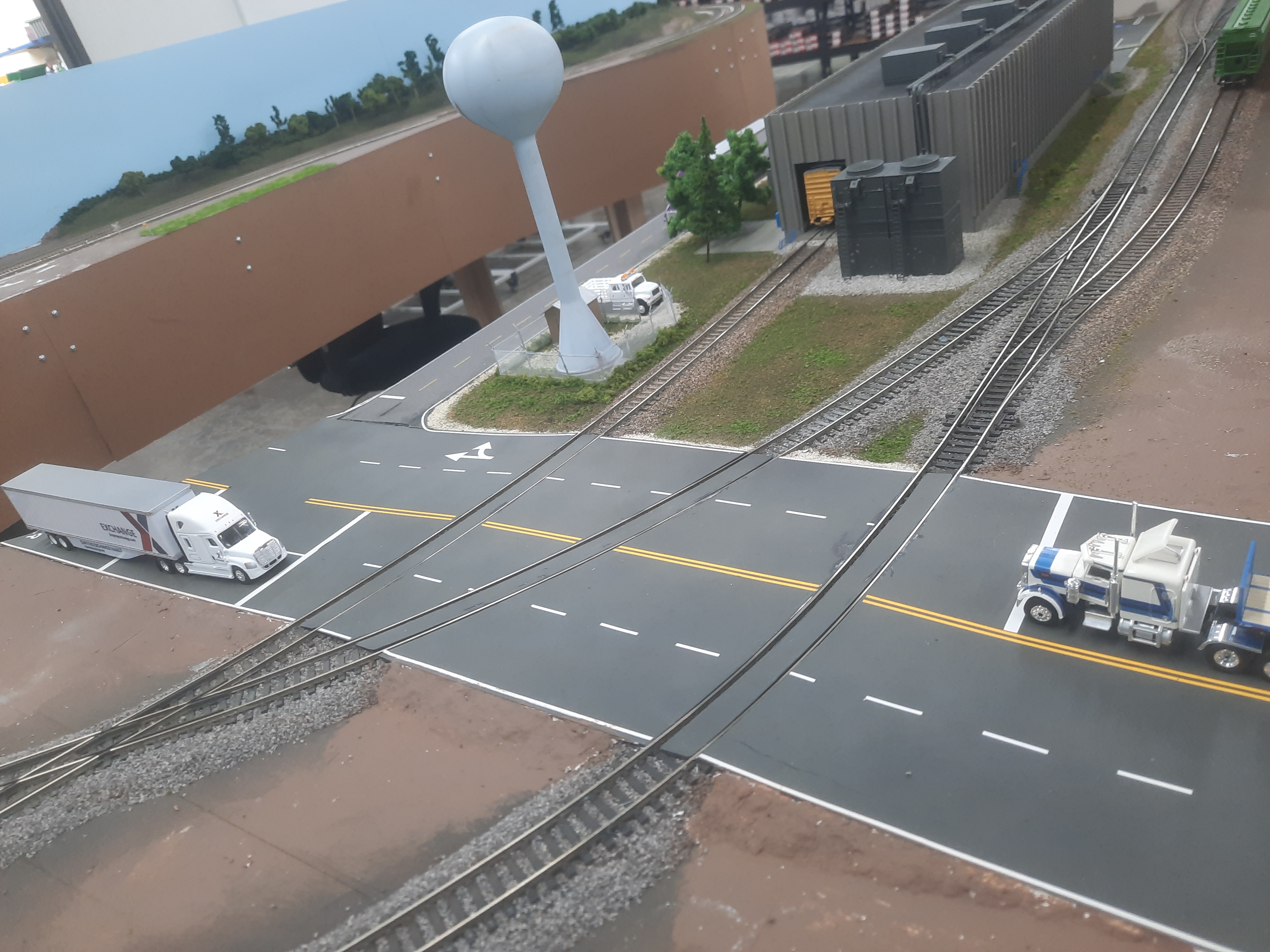
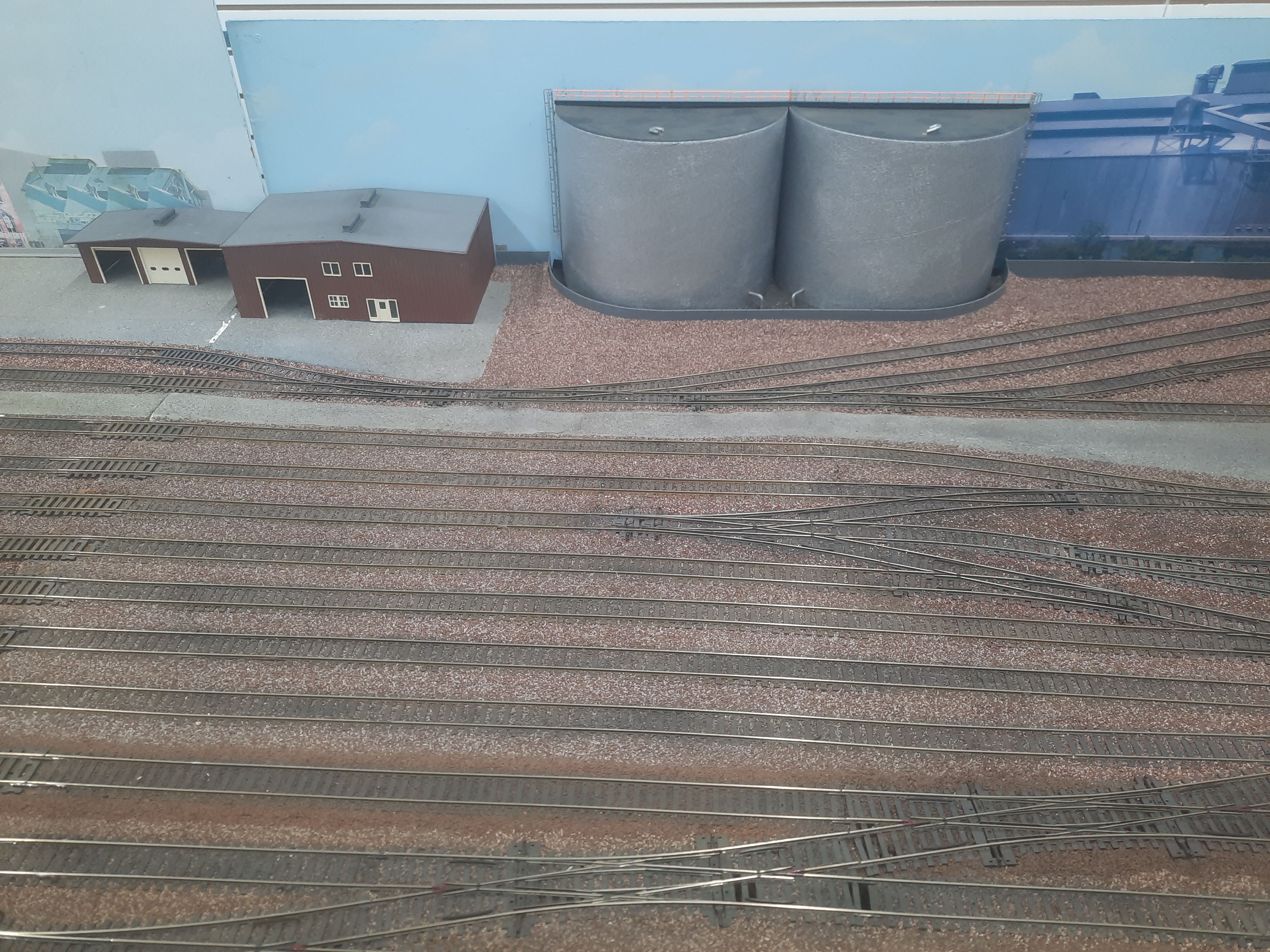
All photos taken of the in store HO layout at Midwest Model Railroad.
Recent Posts
-
Weighting Freight Cars for Better Performance: NMRA Standards, Practical Methods, and Tracking Tips
Weighting Freight Cars for Better Performance: NMRA Standards, Practical Methods, and Tracking Tips
-

Metal vs Plastic Wheelsets: Pros, Cons, and How to Choose the Right Upgrade for Your Model Railroad
Metal vs Plastic Wheelsets: Pros, Cons, and How to Choose the Right Upgrade for Your Model Railroad
-

Weathering Rolling Stock for Realism: Practical Model Train Weathering Techniques That Look Like the Prototype
Weathering Rolling Stock for Realism: Practical Model Train Weathering Techniques That Look Like the